Software Architecture
Software Architecture is the discipline of creating a structured overview of a software system. A software architecture, sort of like a architecture blueprint in real life, shows the different elements, their relations and the properties of these elements and relations.
During the software architecture phase of a software project fundamental design choices are made. Wrong choices in this phase can have implications for the entire software product that might not be remediable without a re-design.
Like architecture in the real world software architecture is equal parts science, craft and art. Below are some principles that should be taken into account. In general there is no one right solution for every problem. Due to different use cases for software systems the architectures also vary.
Principles
Below list of principles is not complete but captures the, in my opinion, most important aspects.
Build to change
Most software projects can and will change their requirements over time. Designing a system that is extendable and flexible enough to address new requirements. Pay careful attention to not overgeneralize though! Building a extensive plugin system for a simple website that only displays static content might be overkill.
Separation of Concerns
The system should be designed in a way that components only handle one specific feature. There should be no overlap in two components functionalities. This avoids interdependency and improves low coupling, making it easier for components to be replaced.
Single Responsibility
Related to the separation of concernes you want one single responsibility per component. The reverse should also hold. Each “action” should have a clearly distinguishable module that is responsible. This helps making the system easier to understand.
Least Knowledge
A component should not need any knowledge of the internal workings (data types, algorithms etc) of a component in order to interact with that component.
Don’t Repeat Yourself
Avoid duplicating functionality in multiple components. Abstract common functionality into a shared module/component to avoid difficulties when trying to change something (i.e. a algorithm) among multiple components.
Group components into logical layers
Group components according to their logical position in a system. For example group together all components accessing the file system.
Define the communication protocol
Define how components will communicate with each other (i.e. via REST APIs over HTTP).
Define the Data format
Define the data format used when components interact with each other. Avoid mixing multiple data formats.
Naming Conventions
Define clear naming conventions for variables, classes and components. Make names easily readable and understandable.
Unified Modeling Language (UML)
Unified Modeling Language (or UML) is a modeling language intended to specify the behaviour and structure of a software. It does this by specifying a number of diagrams that can be used to express workflows and strutures of a software in a visual way.
The number of types of diagrams within UML is vast and (in typical UML fashion) can be represented by a UML diagram itself.
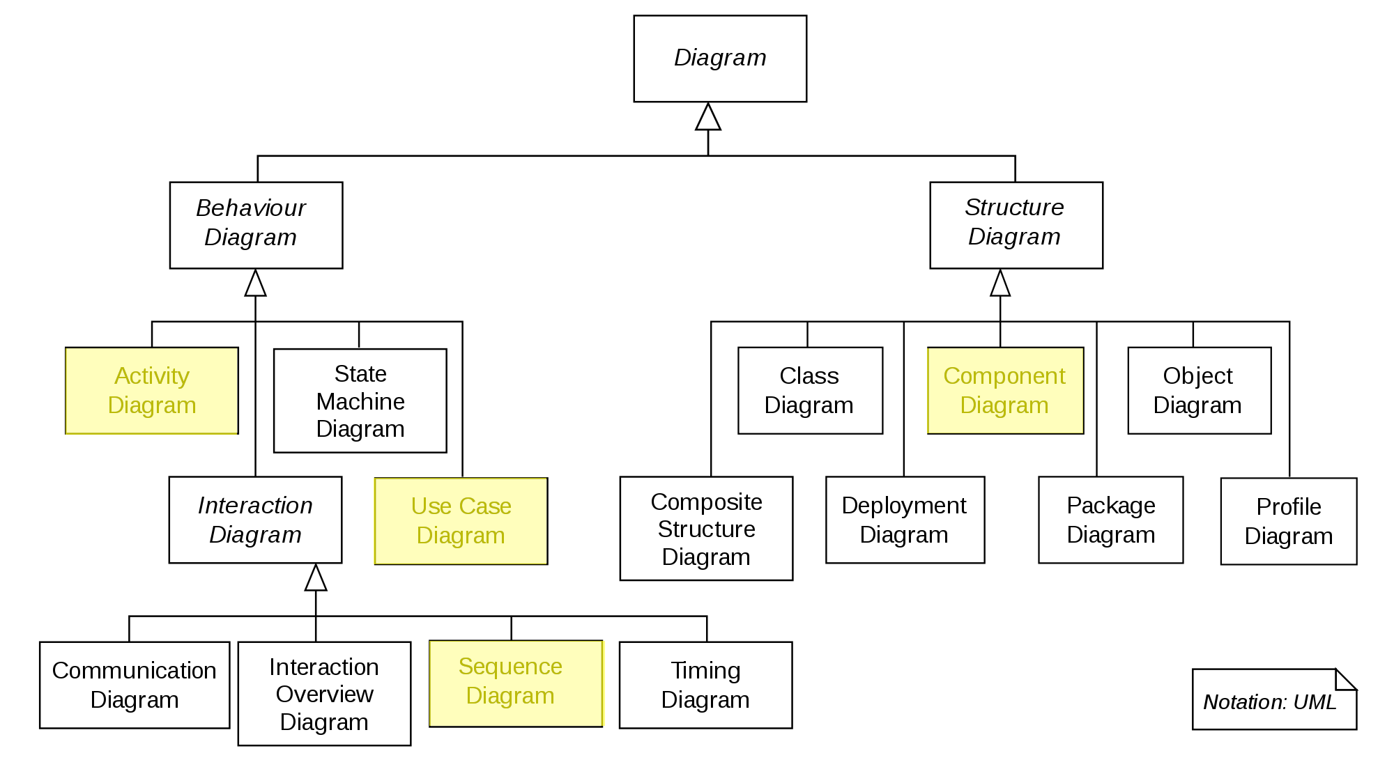
The UML diagram family tree.
There are two families of diagrams. Structure diagrams define the structure of our solution and Behaviour Diagrams define the behaviour of our solution.
In this tutorial we will focus on
- Activity Diagrams
- Use Case Diagrams
- Sequence Diagrams
- Component Diagrams
Component Diagram
Component Diagrams summarize the components of a software and how these components interact with each other. Component Diagrams specify the interface a component provides or requires.
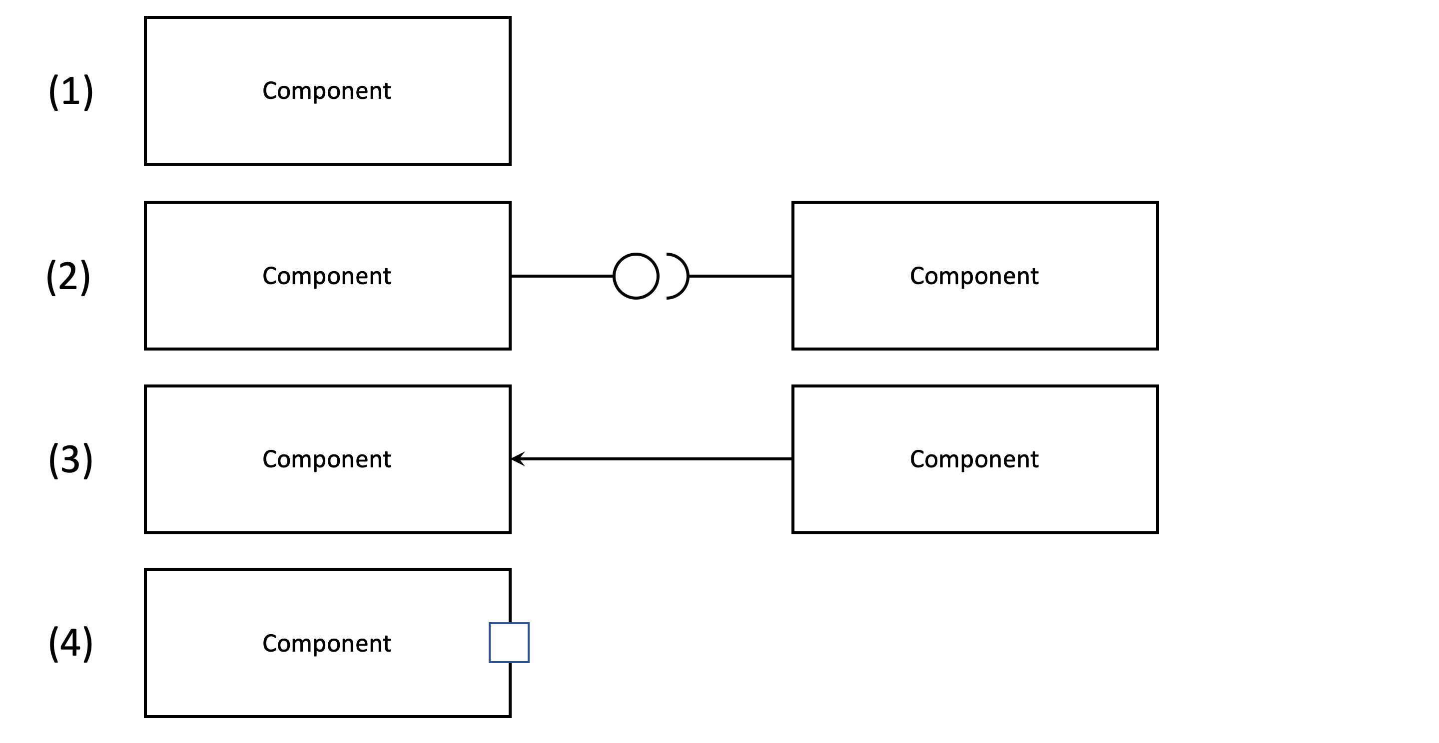
The different types of components in a component diagram. (1) is a simple component. (2) shows the left component defining an interface (symbolised by the circle) and another component requiring that interface (symbolised by the half-circle). (3) shows a component depending on another component and (4) is a “port”. Ports are ways for components to expose functionalities (i.e. via an API).
Use Case Diagram
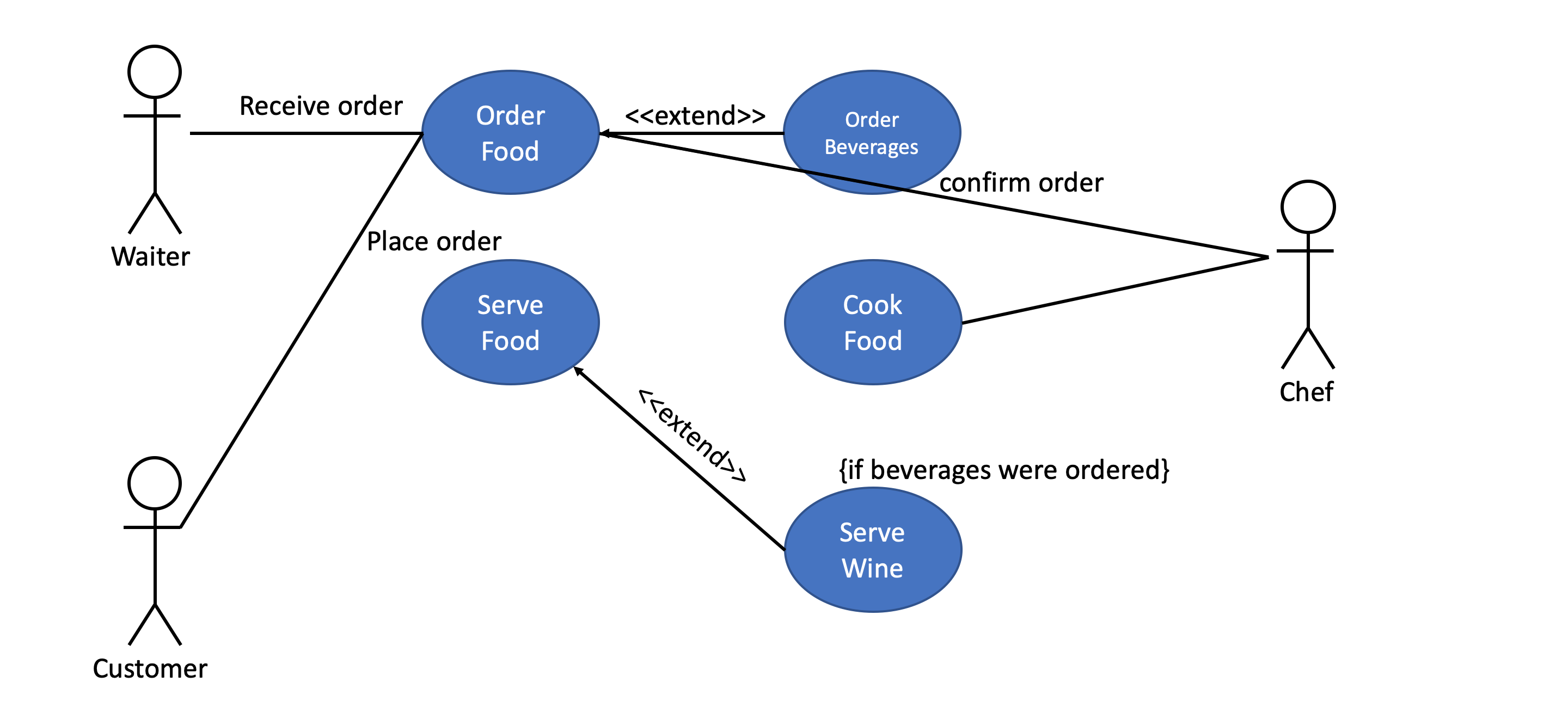
A use case diagram captures all high level use cases and their interactions within a system as well as all actors involved.
The diagram below shows a (truncated) use case diagram for the processes in a restaurant.
Activity Diagram
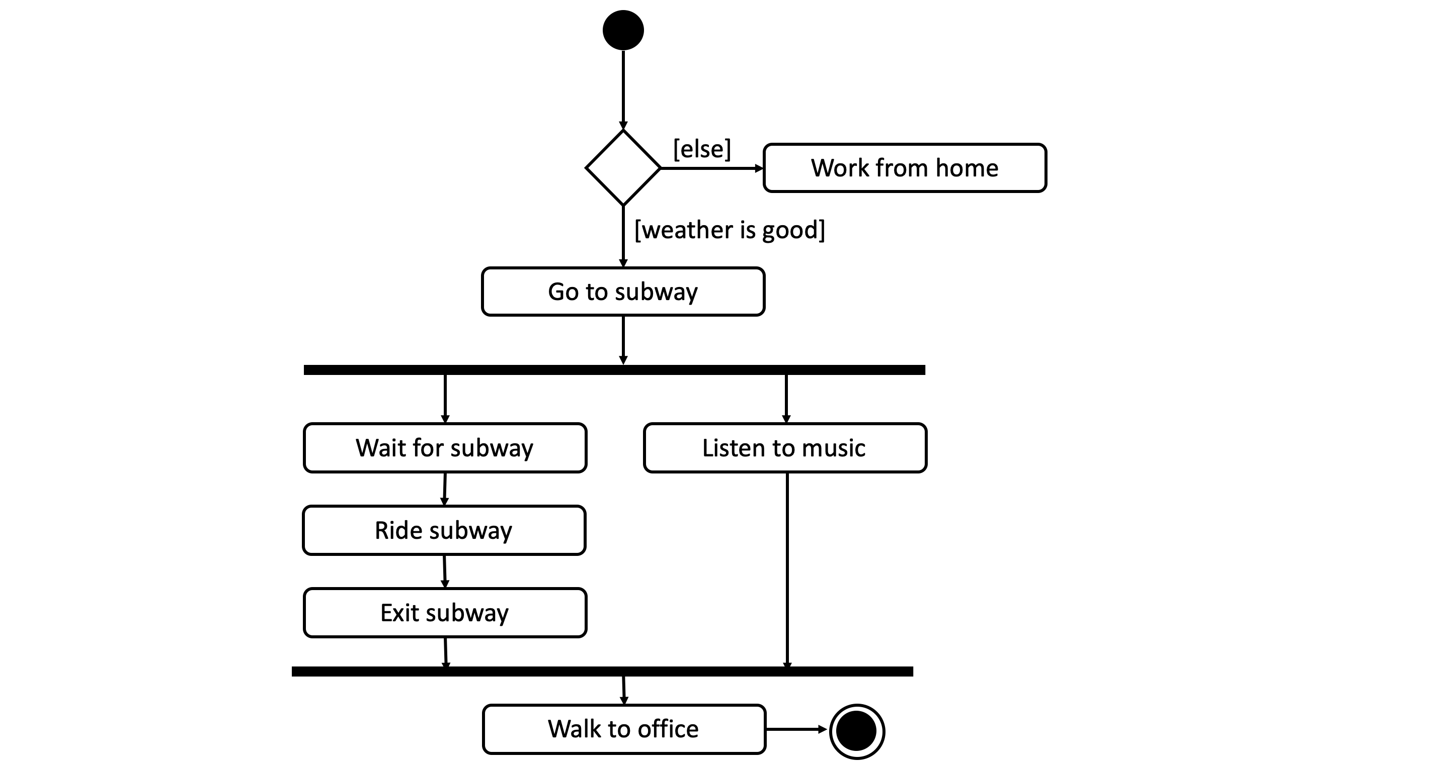
A activity diagram is a graphical representation of a workflow that support choices, iterations and concurrency.
In its intended form activity diagrams can be used to model computational workflows (i.e. program flows) as well as organizational workflows.
In a workflow diagram a
- ellipses represents an action
- diamond represents a decision
- bars represent the start or end of a concurrent activity (parallel execution)
- black circle represents the start of the workflow
- encircled black circle represents the end of the workflow
- arrow represents the flow of the execution
The diagram below shows the workflow for coming to the office.
Sequence Diagram
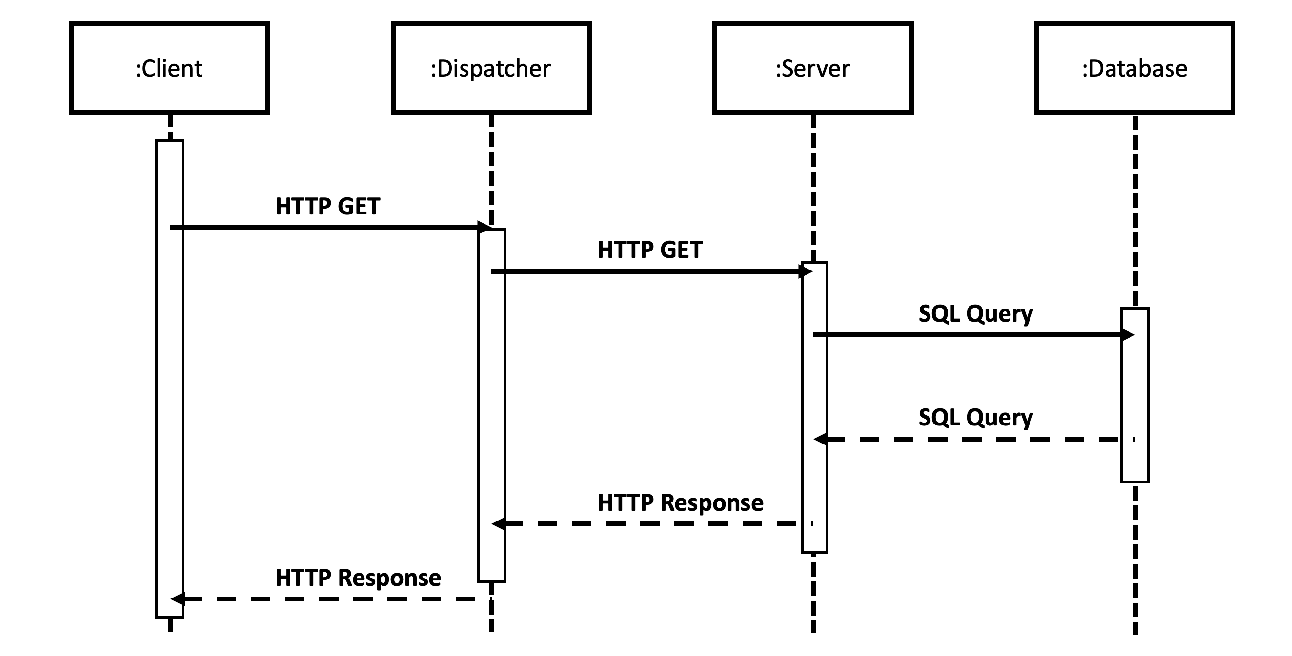
A sequence diagram shows the interaction between objects (or components) in the fashion of a timeline. They usually represent one use case. They are sometimes also referred to as event diagrams or event scenarios.
The main building blocks of these diagrams are:
- Lifeline the vertical lifeline represents the lifespan of this object/component
- Blocks the object(s) that interact with each other
- Messages written on horizontal arrows to display a interaction between two components. Blocking (or synchronous) messages are represented by a full arrow had, non-blocking (or asynchronous) messages are represented by open arrow heads. Responses are dashed arrows.
- Activation boxes are rectangles placed on top of the lifeline that show a computation being performed
The diagram below shows an example sequence diagram for a HTTP request to a web server with a attached database.